The Saber Card

The Credit Card Sized Mini-Kit

The Saber Card is designed to teach you how to solder, remove and replace surface-mount components using basic tools. As nearly all electronic devices use these tiny components, learning to solder and desolder them is essential if you want to have a go at fixing your electronic devices instead of throwing them in the trash.

This kit uses 0805 LEDs, Resistors and Capacitors that can be soldered, removed and replaced using a soldering iron. The two SOP integrated circuits can be soldered using a soldering iron. Removing and replacing the SOP components can be done using a heat gun. 

We have provided a video tutorial to show you how to solder and desolder these components. We  have also provided a detailed manual that includes a description of the circuit and how it works, a BOM (Bill of Materials), schematics, written assembly instructions, and a component index that describes each component, how they work and how to troubleshoot them.

When you are confident with soldering surface mount components, why not try our other kits that include some surface mount components: 

The Motherboard kit features an optional micro-USB socket for power and optional LEDs for each IO pin.

The Sensor Array includes a Micro-SD card slot to save sensor data over time. 

Astable NE555 Frequency Calculator

Use this calculator to calculate the frequency, in Hertz (number of cycles per second), of the clock signal generated by the astable 555 timer circuit. This will determine how quickly the 4017 decade counter will cycle through the LEDs. 

The calculator uses the following formula: 

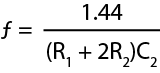
Remember to convert your values to Ohms and Farads. Divide kΩ by 1000 and uF by 1,000,000.

To find R1, R2 and C2, take a look at the schematic and the circuit diagram in the manual above. The values can be changed to suit your preference. 

LED Resistor Calculator

Use this calculator to calculate the minimum resistance needed to protect your LED.  

The calculator uses the following formula: 

The forward voltage of the LED (VLED) can be found in the datasheet. The LEDs in this kit have a forward voltage of 3.2V.

The LED’s max forward current is 30mA (0.03A) and the datasheet’s measuring conditions use 20mA (0.02A). You can aim for anything below 20mA to make the LED last longer. A resistor value can be chosen depending on the required brightness.