


ATMega328P specs:
- 8 Bit microcontroller
- Advanced RISC Architecture
- High Endurance Non-volatile Memory Segments
- 23 Programmable I/O Lines
- Six PWM Channels
- 28-pin PDIP Package
- Operating Voltage: 1.8V – 5.5V
- Power Consumption: 0.2mA in active mode
- DC Current per pin: 20mA
- Flash Memory: 32KB (0.5KB used for bootloader)
- SRAM: 2KB
- EEPROM: 1KB
- Clock Speed: 16MHz
- SPI interface (Including I²C)
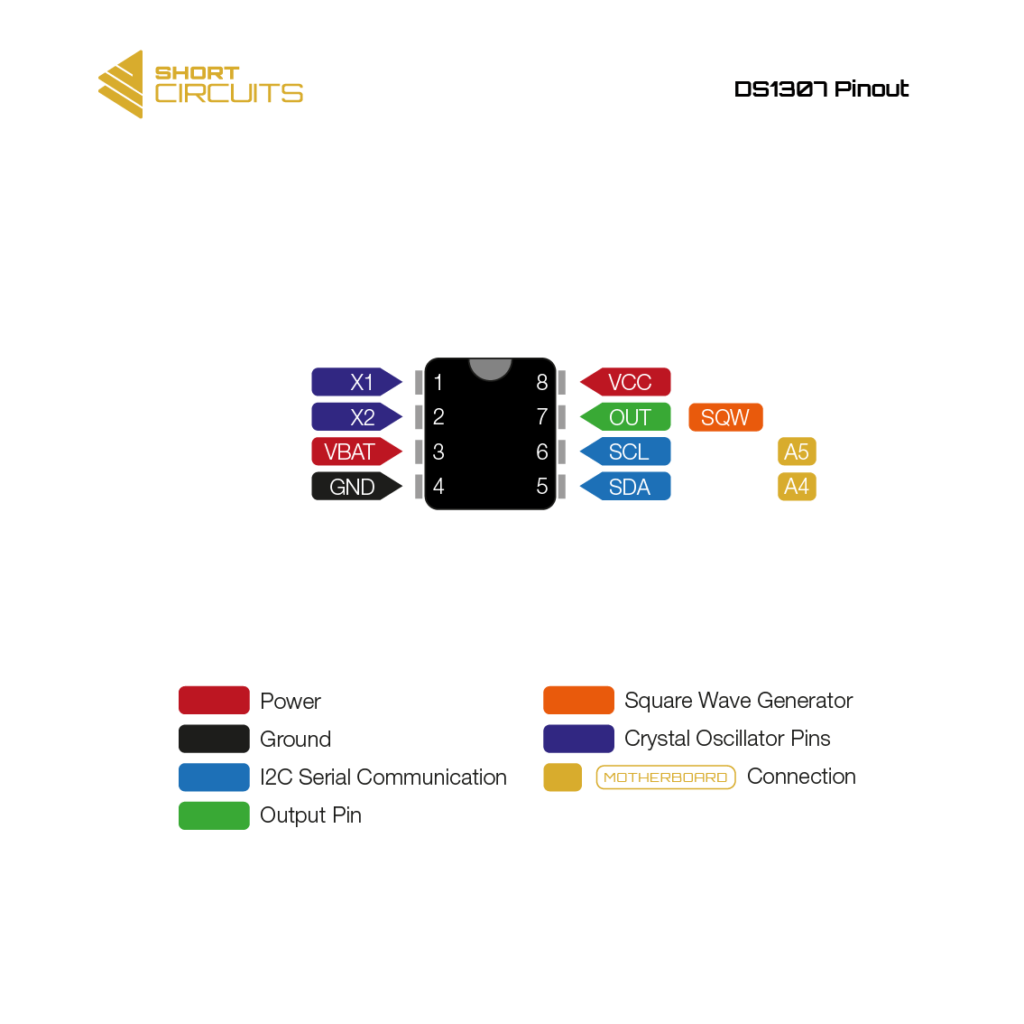
DS1307 Specs:
- Completely Manages All Timekeeping Functions
- Counts Seconds, Minutes, Hours, Date of the Month, Month, Day of the Week, and Year with Leap-Year Compensation Valid Up to 2100
- 56-Byte, Battery-Backed, General-Purpose RAM with Unlimited Writes
- Programmable Square-Wave Output Signal
- Simple Serial Port Interfaces to Most Microcontrollers
- I²C Serial Interface
- Low Power Operation Extends Battery Backup Run Time
- Consumes Less than 500nA in Battery Backup Mode with Oscillator Running
- Automatic Power-Fail Detect and Switch Circuitry