


USB Power ![]()
You can power the board through the Vcc and GND terminal blocks. But USB is more convenient. It is a difficult part to solder, but don’t worry, if you mess it up, you can snip an old USB cable and connect the red and black wires to the terminal block’s VCC In and GND respectively. This USB socket is not used to communicate with a PC. The data connections aren’t connected. This is because the ATMega328P can’t communicate directly through USB. You need to use a Serial to USB board or a more feature-packed microcontroller to translate for the 328P.
5v Input ![]()
This is where a regulated 5V can be connected to The MOTHERBOARD (and any other Boards connected to the 5V Output). This could come from your favourite bench power supply, or our upcoming POWER BOARD, which provides 5v (for all the 5v components in our circuit), and a variable voltage from 1.2v up to 20v+ (for most other needs). As mistakes do happen, we’ve added a Zener Diode and a Fuse to protect the rest of the circuit from overvoltage. If the voltage exceeds the breakdown voltage of the diode (5.1v), current will start flowing through the Zener to ground, rather than the rest of the circuit where it can damage components. This will in turn increase the current draw to a point that would trip the fuse and save your components. (See Component Index for more info)
5v Output ![]()
Here we have a convenient 5v output, to power all the other boards that you want to use with your microcontroller. Power the DIGITISER, the RGB MATRIX, the SENSOR ARRAY, or any other board we produce. Boards powered from these outputs also benefit from the voltage protection circuit we added to the 5v input.

 Ground Planes
 The back of the board is covered with a layer of copper that is connected to GND. This is called the ground plane. We add this for a few reasons. One reason is that it’s just easier to design that way. When you need to connect something to ground, just connect it directly to the ground plane underneath the component. That way you don’t have to worry about adding any ground traces all the way back to the power input. If this was a 4-layer board, then a 5V plane would also be a good idea. Another reason is to add some electromagnetic shielding to the circuit, this reduces the chance of erroneous results due to the effect of electromagnetic interference on our circuit.
Design Considerations
When laying out power traces, and the components themselves while designing PCBs on the computer, it is important to consider current loops. When electric current moves around your circuit, it can create electromagnetic interference (EMI). This messes with some sensitive components. The larger the loop, the more EMI is caused. This is one of the reasons why using the bottom copper layer as one big ground plane is preferable. This way, the current can take the shortest and most direct route back to the power supply. Try and make the 5V traces as direct as possible. When we designed this circuit, we had to balance this with readability, so our boards aren’t optimally designed for EMI.

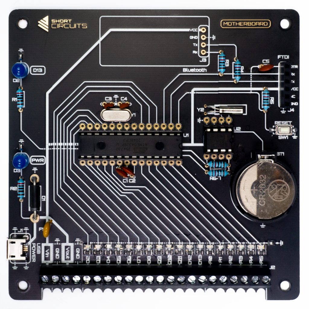
ATmega328P Microcontroller ![]()
The ATmega328P is the brain of our circuit. This chip can read changes in the voltage at its input/output pins and also set them to a chosen value. Using the Arduino programming software, we are able to program it to respond to inputs from other modules and send responses to other modules as outputs. This gives us the ability to create unlimited ways to manipulate other devices to build and program useful gadgets. You could read data from a Real Time Clock module then process the data to send to a 7-Segment display… A Digital Clock! Or you could read the data from a thermometer and process that data to send to an RGB LED array… A Graphic Thermometer! The possibilities are near endless!
Bypass Capacitor C1 ![]()
A decoupling capacitor. It’s function is to smooth out any noise (spikes or drops in voltage) due to other components affecting the power supply to the microcontroller. It ‘decouples’ the chip from the other parts of the circuit. It does this by holding an amount of charge and releasing it when the voltage drops, to compensate. It is placed between power and ground, as close to the IC’s (Integrated Circuit) pins as possible.
Bypass Capacitor C2 ![]()
This is another decoupling capacitor that makes sure the analog reference voltage (AREF) measured from pin 21 of the microcontroller is at a steady value. In our case, that value is the same as our reference ground, or approximately 0v.
Crystal Oscillator ![]()
The crystal oscillator mechanically oscillates to provide a square wave signal at a stable reference frequency. This is used by the microcontroller as a clock signal, or its heart beat if you like. It determines how many times a second the microcontroller can do the actions needed to execute instructions.
Pin 1 ![]()
The pad for the first pin of any IC footprint is usually indicated by a square pad. Other indications are the semi-circle on DIP ICs or some other mark close to the first pin. When oriented correctly, the first pin is on the bottom left. The microcontroller in this circuit is oriented upside down due to the design of the PCB, so make sure you check this before soldering the IC socket and inserting the chip. Pins are numbered anti-clockwise.
Load Capacitors C3, C4 ![]()
These are the load capacitors for the crystal oscillator. They are reactive components that help create the feedback loop that enables the crystal to start oscillating at the intended frequency.
Reset Switch & Pull-Up Resistor ![]()
This resets the microcontroller. A Single Pull Single Throw switch with a 10K Ohm pull-up resistor. This switch pulls the RESET pin on the microcontroller to ground (0V) when pressed. This resets the microcontroller. As electricity takes the path of least resistance, when the switch is not pressed, the only path is to VCC (5V) through the 10K resistor. When the switch is pressed, the easiest path is to ground. If the resistor wasn’t there and the switch was pressed, there would be an uninterrupted path from VCC to GND. This is a short circuit, and will probably burn out the microcontroller.