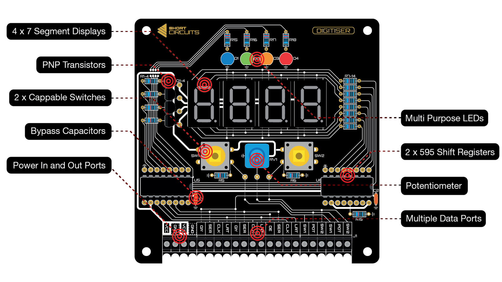
The DIGITISER is a versatile display and input board. Can be used as a number display for a clock, stopwatch, or count down timer (With the RTC on board the MOTHERBOARD), temperature, relative humidity, light and sound meter (Using the SENSOR ARRAY), or a simple score counter for your favourite card games. The DIGITISER uses 2 HC595 Shift Registers to drive 4 common anode 7-segment displays. PNP transistors are used to source current from the main supply while only requiring a small amount from the Shift Registers to switch them. With the 4 spare Shift Register outputs, we decided to add 4 coloured LEDs to act as mode indicators or whatever else you can come up with. 2 Switches and a potentiometer add some input options for what is likely to be front and center for a lot of builds. As with any of our kits, this one comes with an extensive manual.
Through-Hole Test Points at key points in the circuit
Designed to be easy to follow and understand
4 x 7-Segment Displays (Common Anode)
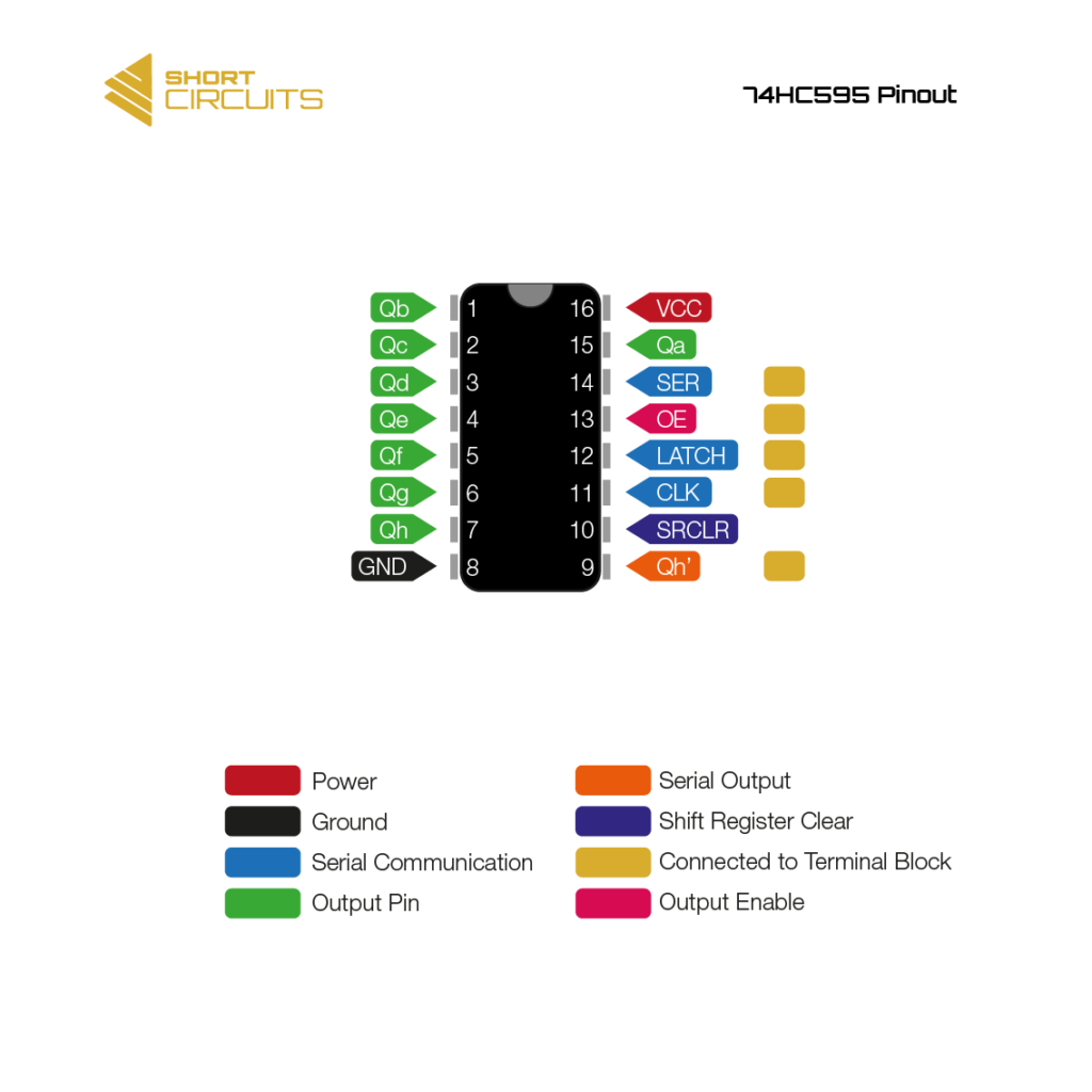
2 x 74HC595 Shift Registers for Serial in, Parallel out
PNP Transistors to source current for the common anodes
Bypass Capacitors on each Shift Register to filter out interference
4 different coloured LEDs for mode indicator, ambient volume indicator (Using the microphone on the SENSOR ARRAY) etc.
2 Switches for mode select, incrementing numbers etc.
1 Potentiometer to change displayed value, or as a mode select, dimmer etc.
Multiple IO ports for neater wiring to other boards
Output Enable pin will be available for PWM dimming
40+ page manual with every part of the circuit and every component explained in an easy to follow way
Height and Width: 100mm x 100mm
Stacks/Panels with other Short Circuit Boards
Clearly printed traces to aid understanding of the circuit and to help with fault finding
Back of board is printed with the circuit so you can see every trace, even when the components are soldered on. This makes it easier to understand and to fault find
We use cookies on our website to give you the most relevant experience by remembering your preferences and repeat visits. By clicking “Accept”, you consent to the use of ALL the cookies.
This website uses cookies to improve your experience while you navigate through the website. Out of these, the cookies that are categorized as necessary are stored on your browser as they are essential for the working of basic functionalities of the website. We also use third-party cookies that help us analyze and understand how you use this website. These cookies will be stored in your browser only with your consent. You also have the option to opt-out of these cookies. But opting out of some of these cookies may affect your browsing experience.
Necessary cookies are absolutely essential for the website to function properly. These cookies ensure basic functionalities and security features of the website, anonymously.
Cookie
Duration
Description
cookielawinfo-checbox-analytics
11 months
This cookie is set by GDPR Cookie Consent plugin. The cookie is used to store the user consent for the cookies in the category "Analytics".
cookielawinfo-checbox-functional
11 months
The cookie is set by GDPR cookie consent to record the user consent for the cookies in the category "Functional".
cookielawinfo-checbox-others
11 months
This cookie is set by GDPR Cookie Consent plugin. The cookie is used to store the user consent for the cookies in the category "Other.
cookielawinfo-checkbox-necessary
11 months
This cookie is set by GDPR Cookie Consent plugin. The cookies is used to store the user consent for the cookies in the category "Necessary".
cookielawinfo-checkbox-performance
11 months
This cookie is set by GDPR Cookie Consent plugin. The cookie is used to store the user consent for the cookies in the category "Performance".
viewed_cookie_policy
11 months
The cookie is set by the GDPR Cookie Consent plugin and is used to store whether or not user has consented to the use of cookies. It does not store any personal data.
Functional cookies help to perform certain functionalities like sharing the content of the website on social media platforms, collect feedbacks, and other third-party features.
Performance cookies are used to understand and analyze the key performance indexes of the website which helps in delivering a better user experience for the visitors.
Analytical cookies are used to understand how visitors interact with the website. These cookies help provide information on metrics the number of visitors, bounce rate, traffic source, etc.
Advertisement cookies are used to provide visitors with relevant ads and marketing campaigns. These cookies track visitors across websites and collect information to provide customized ads.